The only challenge here is figuring out witch motor should go to each board.
Pictures:


Next step, the Plastruder.

The wiki says: *TIP* If the rods are too short they will move back and forth causing loss of resolution and additional noise. If this is the case for you, just insert something between the end cap and the rod to help compress it.
Well I put one of the M3 nuts in each of the two caps to press the rods into position.
Some images:

Tips for others:
The only problem I ran into (apart for the screw) was that when I made sure there was 1 mm clearance between the drive pulley and the motor the timing belt was not level with neither the Y-stage nor the idler pulley. I moved the drive pulley several mm’s up until it was level with the rest.
That was not a major problem as it was easy to reposition it, but it was time consuming to get the drive pulley to be 1 mm above the motor.
The parts laid out:
This part was very simple and straight forward.
The only two problems I ran into while making the Y-stage was
Tips for other builders:
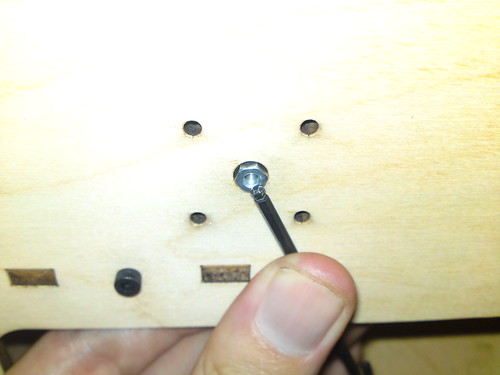
Some images from the process:
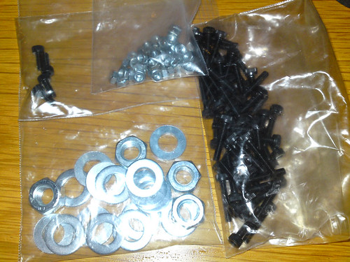
All parts laid out before:
Got my MakerBot in the mail.
It is made in batch XVI (hint the batch number is etched into the wooden parts, unlike the serial number it is not printed on a label)
Decided I should name it Fermat (in honor of Pierre de Fermat)
Also stared reading the build instructions and consider if I should paint it or not … the decision is to not paint it for now, maybe try to give it some protective lacquerer later on (not a optimal plan – if you know you want to paint your – do it before starting assembly).
Important: If you have gotten a kit that includes a power supply. Make sure you verify that it is set for the correct operating voltage – if not you will release the magical blue smoke from it.
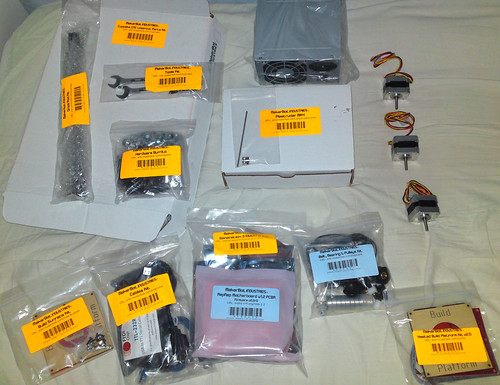
All parts of the MakerBot (deluxe kit, no plastics plus a heated build platform and a extra Plastruder MK 5 gear upgrade kit) laid out on my bed:
